If you follow me on Instagram, you know that I’ve been collecting vintage gear for a while now. I bought my ARP Omni MK1 a few years back from one of the former members of Kleeer. Unfortunately, it wasn’t used on any of their recordings and was purchased by the owner YEARS after the band broke up.
For those unfamiliar, the Arp Omni was one of the best selling synths of the 70’s and used on countless disco and prog rock records. I’ve used it on plenty of beats (check this one here for an example). While it was partially re-capped when I bought it, a lot of the internals were original (tantalum capacitors meh) and I was starting to get some weird behavior lately. Despite only being semi-decent at soldering and only knowing basic multi-meter functionality, I decided to purchase a bunch of kits on Synthchaser.com to bring it back to it’s former glory and add some new functionality.
So what happened? I screwed up several times lol… but I eventually learned way more than I thought and it’s now functioning better than ever. Hopefully this serves as guide of helpful tips if attempting any vintage synth repair and what NOT to do. Here’s the story….
The Prequel
About 2 years ago the push button switches started to go. Buttons wouldn’t stay “clicked” and had to pushed several times to get them to lock. I bought a full set of replacement switched and was able to install them without any issues.
Last year, the sliders became increasingly more stiff and hard to move. I de-soldered the worst ones and dissembled/cleaned. Again – success!
Early 2023
More sliders were stiff and I was getting some weird feedback noise. Also, the power supply was getting unreliable. Since I was able to “repair” a few things before, I felt confident enough to overhaul the entire thing. This included:
- Full Capacitor Recap (all boards, power supply, etc)
- Full IC replacement
- New LED Sliders
- Correct the VCF board (factory cutoff frequency)
- Replace All TDA407 chips
Unfortunately, things did not go as planned…
Part 1 – Upper Boards
Armed with nothing but a soldering iron and solder braid, I started with the Power Supply board. There were only a few components to replace on here and it went smoothly.
From there I went to the Synth Control board. Again, only a few parts to replace and no major issues.
My first issue came when I hit the String Control board. The new LED sliders required tapping into the 15+ volt power rail for the lights and a ground. I soldered the wire to what I thought was the power but it wasn’t. Result? Every time I hit a key, the voltage dropped and the LED slider lights dimmed lol. It was at this point I downloaded the schematics and tried to decipher them (had no background in this at all!) I eventually found the correct solder point and LEDs were working as expected.
The Synthesizer board was next… this included removing the 4075 VCF module and installing the “correction” resistor for the higher cutoff frequency. Everything still good…
Finally, was the Phaser board. No issues here either.
Part 2 – Expensive Lessons
Now that the top half of the keyboard was working, I decided to tackle the Upper Voicing Board. The capacitor replacement was fine, but the IC chips… there were a lot. It was at this point trying to desolder with a braid was getting ridiculous. It would take upwards of 30 minutes each just to get the chips out. After a few days, I finally managed to get them out and replace with the new ones. Turn the synth on and… half the keys no longer work. Hitting notes gets no sound or the same note… what did I do!?
It was time to really start reading the schematics to try to figure it out. In preparation, I re-ordered a full set of IC chips because I obviously messed up one of them. I also decided desoldering all of these chips with a braid was futile. It was time to cough up the money for a Hakko desoldering iron. Wish I had this from the beginning because it would have sped up the whole process, but I digress…
So I have the board out trying to test continuity and now the synth won’t turn on. I look around and noticed I snapped the legs off of one of the power rail film capacitors on the Lower Voicing Board. Ordered replacements for that…
Moving the board around some more, I noticed a broken resistor that controls the voltage when a key is depressed. This one just crumbled from old age. Ordered those next…
Finally, I noticed a broken germanium diode on the Upper Voicing Board, which also must have cracked when moving the board around. For those that don’t know, they don’t really make germanium diodes anymore so had to replace with a silicon diode.
Part 3 – Let’s Try This Again…
Finally got all the replacement parts and started removing/replacing each of the IC chips on the Upper Voicing Board, one by one… Of course, the last IC chip was the issue. It’s the chip that’s responsible for taking the signal from the oscillator and sending out to all of the divider chips. As anyone who has worked on vintage Arp synths can guess, the culprit was a lifted trace. I replaced the chip and created a proper jumper. Plug the synth back in… it works! But wait, I don’t have any string sounds…
I decide to push on and replace the chips on the Lower Voicing Board hoping it resolves the issue. Of course not, same status. After staring at circuit boards for weeks, reading the schematics finally “clicked” in my brain and I actually understood what I was looking for. I traced the issue back to something on the Synth Control board. Time to order some more replacement ICs… I also decided to buy some IC sockets so next time a chip is bad, I can easily replace.
Found the issue with an IC again. This time, it was the one responsible for taking the switch voltage inputs to enable/disable the voices. Wasn’t a lifted trace, was just a bad chip :shrug: While moving things around and moving jumper wires to figure this out, some things that shouldn’t touch each other, touched and… SPARKS!
Part 4 – 1 Step Forward, 2 Steps Back
I turn the synth back on and I have string voices! But… I have no synthesizer voices. I start tracing the signal path and I find that the audio signal is making it to the Synthesizer Board but dying there. Did I fry the IC chips? I sure did! Well, at least the LM301 OpAmp chip. After replacing, the signal left the board but stopped at the VCF 4075. I clearly fried it. Instead of rebuilding, I threw in the towel and ordered the drop-in replacement from Synthchaser.com.
The synthesizer voices worked again! But now the string section was always on regardless if the voice switches were enabled. Again, ANOTHER bad IC Chip on the String Control Board. After replacing, I was finally ready to close this out.
Part 5 – Odds and Ends
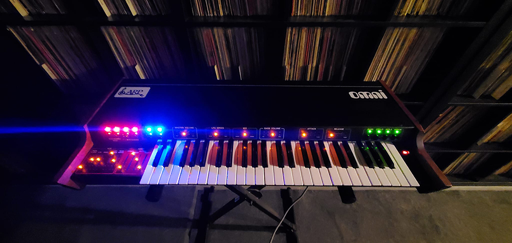
First, I decided to replace a bunch of the film capacitors that looked off or the if the legs looked ready to snap. Then, I went back and replaced the TDA407 chips (with IC sockets too!). Finally, for some flair I replaced the original push button LEDs with some brighter ones and switched the color for the Phaser and Waveform buttons. One thorough cleaning of the keybed and it was FINALLY done.
Summary
Overall, from start to finish it took me about 7 weeks to get the synth back up and running. I did decently learn how to read a schematic, use more advanced functions of a multimeter, and get a general sense of how these old synths work. Do I recommend you do it? Probably not lol But be warned, if you come across an Omni many repair shops won’t work on them for the reasons you saw in my story. If you do decided to embark on this journey, I recommend you do the following…
- Don’t attempt this without a Hakko Desoldering gun or an equivalent. Solder braid and manual suction pumps won’t cut it.
- Download the schematics, read the schematics, live the schematics
- Get a multi-meter and learn how to use it.
- Buy this – not an ad but this thing is awesome
- Watch for static, short circuits, etc… IC chips are more sensitive than I imagined.
- Be careful with the film capacitors when moving the boards around. The legs are short and snap easily. Same goes for any of the other components. This thing is from 1976, give it a break.
- Buy IC sockets. I wish I installed them for ALL the chips. Would have made my life easier.
- Watch for lifted traces.
- Seriously, watch for lifted traces and when you inevitably lift one, jump correctly.